|
|
|
|
Tips of the trade from the Charger group |
|
 |
Vapor Lock There's a couple of things you can do to help prevent vapor lock. The first, is to understand the dynamics of what is happening. The gasoline in the fuel line gets super heated and begins to "vaporize" in the line. It literally "percolates". When this happens, the fuel pump cannot "pump" a steady stream of vapor, air & fuel. So, it "vapor locks". When you pull over to the side of the road and idle the motor you are taking all the load off the system. It only has to cool down a few degrees for the symptoms to disappear. Now that you know what vapor lock is, how does the fuel get heated. This is something that can drive a person crazy! Sometimes, when new lines are run from the tank or if new exhaust systems are installed (particuarly headers) they come into close contact with one another. NOT! This can't happen! Vapor lock can occur. On Mopars, when the fuel outlet tube from the fuel pump is routed to the carburetor, it sort of makes a vertical bend upward on the left front side of the motor (facing the front of the engine). Sometimes, this tube is too close to the engine block and/or the upper radiator hose and/or the heater hoses and the line can become super heated. So what do you do? Climb under the car - better yet, put it up on a rack - and determine that the line coming from the tank to the inlet side of the pump is "A-OK" and not too close to any exhaust component. Next, check the outlet line going to the carb. Ensure you're not too close to any hot water hoses and/or engine block or manifold. Next, you can insulate the fuel line (usually the outlet side only) with a wrap to ensure it doesn't get too hot. The same stuff guys use to wrap headers and/or manifolds will work great! Someone already mentioned the fuel filter. Very definately you want to ensure your filter is clean. The best way to keep it clean is to ensure your tank is clean. If you haven't done so already, you may want to remove your tank and have it boiled-out! You can replace all the rubber & gaskets at the same time. If your tank is "gunky" no amount of new filters is going to keep you on the road. Those in-line filters plug really easily. Lastly, ensure your pump is good and serviceable. In extreme cases, you can install an electric pump, but this is no substitute for correcting the real problem. The other thing to look for, and I'm surprised someone didn't tell you, is to replace the fuel pump pushrod if you haven't done so. I would never recommend re-using the "old" fuel pump pushrod after an engine overhaul. They do wear and you'd be surprised just how much this can impact your fuel delivery system! I was talking with the guy who owns "Rare 440" at the reunion and he was complaining how his car was "acting up" and he thought it was vapor lock. Without knowing, I mentioned the fuel pump pushrod. He then pulled it from his pocket and was telling me "that was the culprit". What I'm doing to prevent vapor lock and lack of fuel supply: I'm removing my tank and replacing it with a brand new repop tank. All the the 5/16 fuel lines are coming off the car. I'm buying a new sender unit with the 3/8 fuel suction. I'm going to run all 3/8 stainless fuel line up to the pump - away from the exhaust system! I'm also splicing-in an electric pump (to be mounted in the trunk) to pump fuel to the mechanical pump. The mechanical pump is going to be a H.D. racing pump with 3/8 fittings in & out. I'm going to use a Fram, spin-on fuel filter which is about 5xtimes larger than the little in-line filters. I'm also going to wrap the outlet tube to keep it cool and keep plenty of free air space wherever I can. New fuel pump pushrod too! I hope this will keep me running even on the hottest of days! P.S. - I even had a buddy custom mount a fuel line where he "coiled" the fuel tube around the "cold" side of the A/C line so when the A/C was on, the fuel line was nice and cool. It looked strange as all get out, but it worked fine! And on really hot days he naturally had the A/C on and cruising! Had a really dense fuel mixture going into the manifold too! |
| Trim Removal Starting from the rear of the car. The small pot metal chrome curving down the quarter...is removed by taking out the two (5/16th?) nuts from the inside from the trunk. The next section simply is pried straight up with a pry tool or even a 1" putty knife. The piece on the door...can be removed by prying either end up a little bit, and slide it in the opposite direction of the end you pry. The front fender piece is removed in the same manner. Be very careful of the last piece at the nose of the car. There is a special wire clip at the tip you do not want to bend if you wish to reuse it. That piece will also slide forward. As for the stainless around the windows...I believe there is a tool for this, but if you care to do as I did, I made my own tool. I tool a thin regular screwdriver and bent the tip of it to create a small hook in it. Not a big hook, but maybe about a 20* bend in it. Maybe about 3/4" of the tip. Remove the corner clips first for the windshield. Then starting at one corner, you will be pushing the tip of the tool between the molding and seal from the glass side, not the body side. Once you get it pried up a little, you will (difficultly) see the clips that hold the trim in place. You need to get the tip of the tool into the slot of the clip, and pry it downward. It is difficult to explain, but if you pry the trim up enough, you will see what holds them in. Be VERY careful at not prying too hard. You can kink the trim. As for the drip rail stainless, it is locked in by clipping the top part first, then snaps in at the bottom. So you have to be able to pull the bottom part out first, and work your way down the window. I used numerous tools for this. Screwdrivers, pry bars and even a tile cutting tool. (obviously I improvise a lot when some "special" tools are required) If you do not have the confidence or patience, I would HIGHLY recommend a body shop doing so if it will be painted. |
 |
 |
Drum to Disc Brake Conversion 1962 - 1974 B & E MOPAR DISC BRAKE CONVERSION INSTRUCTIONS THIS IS A PRETTY SIMPLE CONVERSION, BUT IT WILL MAKE A WORLD OF DIFFERENCE TO YOUR MOPARS STOPPING POWER. PLEASE FOLLOW THESE INSTRUCTIONS EXACTLY, AND YOU WILL HAVE A TROUBLE FREE EXPERIENCE. THERE IS A LOT OF STORIES, ABOUT USING 1976-1980 PLYMOUTH VALORE, AND DODGE ASPEN, DISC BRAKE SET-UP. Caliper adapters, Calipers, and 11" (10.87 actual) rotors *will* bolt right up to late A body spindles, and will work just fine ON THE 1962-1976 A-BODIES, OR B-BODY, OR THE E-BODY MOPARS......................... The spindles and upper control arms won't work. PARTS NEEDED: 1. You will either need a 1973-74 E-BODY Mopar as a Donor Car, or a much easier car to find in the Salvage Yards, is a 1973-1976 A-BODY, either a Dart, Valiant, Duster, but these years only. 2. I strongly suggest purchasing New Rotors, most cost about .00 ea, and I also strongly suggest purchasing a rebuilt set of Calipers, about .00 ea, and you can also get a "Loaded Caliper Set", this comes with the Pads, from Auto-Zone, Pep Boys, Discount Auto Parts, etc. 3. I also recommend that your replace both the Inner and Outer Wheel Bearings, and grease seal. 4. New Disc Brake Hoses. 5. A new Master Cylinder Disc/drum ( you must know, what car, and year, that was the donor car ). There is a very important part in your New Master Cylinder, there is a little Black rubber sleeve, about 3/4" in diam. This will go one the Brake Pedel Push-Rod, without this little part, the push rod will not lock into the back of the Master Cylinder . 6. Off the donor car, be sure to take the Proportioning Valve, you will have to replace your existing valve, with the one, you took off the Donor Car. THIS IS A MUST, or you can purchase a Adjustable Valve. This will prevent the Brakes from Wheel Lock up. INSTALLATION: Just remove the Steering Knuckle ( Spindel ) from your Drum Brakes, and replace with the Spindels from the Disc Brake, and install. Bleed your entire Braking system, after you have replaced the NEW MASTER CYLINDER. I strongly suggest "Bench Bleeding the New Master Cylinder, prior to installing on your car, see instructions, that come with the NEW MASTER CYLINDER. Note: Please take the time to read, and understand, what I have outlined, for this project, and Please follow the instructions, this will make your job alot easier, safe, and complete. While we are on the subject of the Braking system, Please inspect the Rear Brakes, and Hardware, Hoses and Brake Lines, and don't forget the rubber brake line, that attaches to the rear end housing, and wheel cylinders. This is the best time, to completely beed the entire brake system, until all the rust, and dirt, isn't present in the brake fluid |
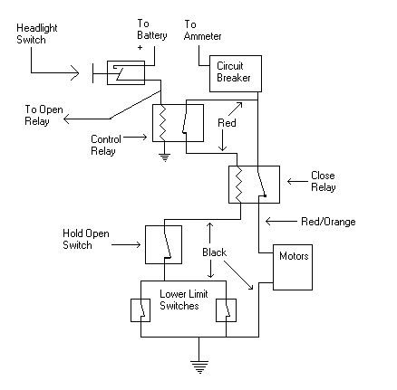
| Headlight Operation This is the corrected circuit from Newt's schematic and a description of how the circuit works on the 1966 and 1967 Chargers. There can be cases where the open and close circuits can try to do the same thing of both opening the doors and closing the doors at the same time if the pick coil is bad on the Control Relay, therefore the entire operation is explained here. Maybe between Allen and my contributions to this monster, then the hair pulling can be cured. Lemme know if you find any errors, and I will fix her up, or for that matter, if I can be of any futher help to anyone. Not saying I have all the answers, but I can try. Now ya'll go out there and fix them headlight motors :) Oh, the jpg file that is attatched to this message is ltgmotor.jpg and is at the end of the reading material. ~ Don ~ OPEN OPERATION Headlight switch (A) turns on the headlights, and the switch energizes the coil on the opening relay (B) via the upper limit switches (F & G) Headlight switch also turns on the indicator light via the upper limit switches (F & G) The headlight switches also operates the Control Relay. The only purpose of the Control Relay is to direct the +12 volts to either an OPEN or CLOSING operation of the doors. With the switch pulled out (ON) +12vdc is applied to the pick coil of the Control Relay and the points open in the Control Relay, and +12vdc is applied down from the ammeter, circuit breaker, through the relay and back up the red wire to junction 3, and then to the left to pin 1 of the Opening Relay. Since we previously picked the coil to the opening relay, the points 1 and 3 are closed so +12vdc is directed to pin 3 of the opening relay and via a Violet wire up to junction 2, and from junction 2 +12vdc is applied to the open winding of both motors. What we need now is current flow through the two motor windings. Plus 12vdc sees ground on the black wire, The motors run until both grounds to the pick coil of the open relay is removed by the rotating headlights that presses the plungers on the upper limit switches. Now lets suppose one of the limit switches is bad (won't close all the way or what we refer to as an open switch) The circuit sees only one ground, and the circuit operates both motors until that one switch that is working opens via the plunger. Then the other motor will stop where it is at which my not be a fully opened position. We now have one headlight pointing down and the other headlight out like it is suppose to be. BAD UPPER LIMIT SWITCH and that needs to be checked with a continuity checker (Ohm Meter). If both upper limit switches are bad (open), then the opening relay coil will not pick via junction 1, and F & G, and +12vdc will not be applied to the open windings of the motors and the indicator light wil not light. CLOSE OPERATION Push in on the headlight switch and the lights turn off and +12vdc is removed from the pick coil of the control relay, and the opening relay. Since the points of the control relay closes, +12vdc from the ammeter and circuit breaker goes out the right side of the control relay via a red wire to the pick coil of the close relay. If the override switch is good and is in the normal mode and not the override position, then the pick coil sees the two grounds via the lower limit switches and the closing relay activates which closes points 1 and 3 together. Now +12vdc is applied via the ammeter, circuit breaker down through the red wire to the control relay pin B, up the red wire to junction 3, over to the right via a red wire to pin 1 of the closing relay, through pin 3 and out on a red wire wuth and orange tracer. Plus 12vdc is applied to junction 4 of the close windings of the two motors. The motors take off and close the doors, until ground to the close relay pick coil is removed by activating the plungers of the lower limit switches. If both limit switches are good then both doors will close. If one of the switches is bad (open), then the doors will stop moving when when the one limit switch plunger is pushed in, and the other door will not be closed all the way. You now know you have a bad limit switch. It is up to you to find the bad switch. If the override switch is defective, then the closing relay will not work and the doors will not close. It is obvious what will happen if the closing relay fails to pick, or operate correctly. The doors will not close. It is obvious what will happen if the opening relay fails to pick or operate correctly. The doors will not open, and the indicator light will stay on. However if the control relay fails to pick when we turn the lights on, we have an interesting results. Plus 12vdc is applied to both open and close windings of the motors. The open windings will see the ground and start the motors moving. Since the points are closed on the control relay, the closing relay is also activated, and +12vdc is applied to the closing windings of the motors. Both the open and close windings will now be trying to run the motor, and my guess is a burned up motor or a tripped circuit breaker. I have no idea what the symptom will be for this "what if", but I do know it ain't healthy for the motors or circuit breaker. I would unplug the headlight motors at this point, and then turn the headlights on. If you have +12vdc at pin H of the control relay, then that is a NO NO with the lights on. Check out the control relay as possibly defective. LOCATIONS The three relays are located behind the glove box and the relay to the left is the closing relay. Relay in the middle is the control relay, and relay to the right is the open relay. The circuit breaker is located behind kickpanel on the drivers side behind the emergency brake. There is a connector beside of the battery that will disconnect the entire grill wiring from the car, and this connector can be accessed for trouble shooting purposes. Disconnect the connector and then you can apply +12vdc to the violet wire to see if the motors will open, or you can apply +12vdc to the orange wire with the red tracer to see if the motors will close. This will let you know if the grill circuit is working correctly. The wires from the grill circuit does not go through the three bulkhead connectors, but instead goes through a hole above the three bulkhead connectors. Hope this helps find the problems that WILL arise with the rotating headlight wonders. |
 |
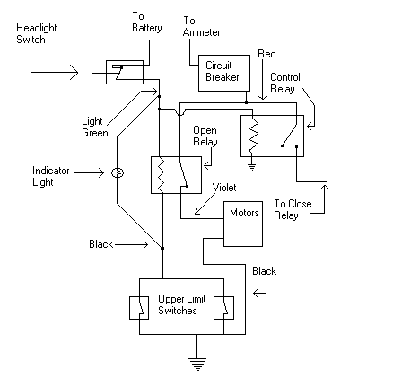 |
Headlight Theory of Operation Theory of Operation, Troubleshooting and Diagnosis of the Rotating Headlight Circuit of the '66/'67 Dodge Charger Introduction: Wow, that's a hell of a title. Anyway, the goal of this article is to provide information regarding the rotating headlight circuit of the First Generation Charger (1966-1967) and assist the owners of these vehicles in restoring and maintaining the function of the rotating headlights. Definition of Terms: Relay: A relay is an electromechanical device which allows a low-current switch to control a high current switch. A relay has an electromagnetic coil which can open and close a mechanical switch when the coil is energized and de-energized. Normally Open: this is a switch or relay whose contacts are open in it's normal, or passive, state. The OPEN and CLOSE relays are normally open, as is the Headlight switch. Normally Closed: this is a switch or relay whose contacts are closed in it's normal, or passive, state. The CONTROL relay is normally closed, as are the Hold Open and Limit switches. Description of Circuits: Alright, this is the start of the good stuff. The OPEN circuit is the less complex circuit, so we will cover that first. Open Headlights Circuit When the headlight switch is closed (turned on), it allows current to pass to the Light Green circuit. This circuit feeds the headlights and the Open and Control relays. The Light Green circuit energizes the Control Relay coil, which opens the contacts and turns off power to the Close Relay coil, shutting down the Close circuit. The Light Green circuit also provides power to the Indicator Light. Finally, and most important, the Light Green circuit energizes the coil of the Open relay which closes the Open Relay contacts. The Open relay contacts energize the Violet circuit, which energizes the Open windings in the Motors and makes the Motors turn in the Open direction. The headlights keep turning until they hit the Upper Limit Switches. When BOTH of Upper Limit Switches are opened by the Motors, the ground path is taken away from the Open Relay, de-energizing the Open Relay coil. This causes the Open Relay contacts to open, and shuts off the Motors. . The switches also shut off the ground for the indicator light, turning off the light. Close Headlights Circuit When the Headlight switch is open (turned off), this de-energizes the coil of the Control Relay, which allows the contacts to close. The Control Relay contacts energize the coil of the Close Relay IF the Hold Open switch is closed. If the Hold Open switch is open, then there is no path to ground for the Close Relay, the Close Relay coil cannot energize, and the Close circuit is disabled. When the coil of the Close Relay is energized, this closes the Close Relay contacts, which energizes the Red/Orange circuit. The Red/Orange circuit energizes the Close windings in the Motors, causing the Motors to turn in the close direction. When BOTH of Lower Limit Switches are opened by the Motors, the ground path is taken away from the Close Relay, de-energizing the Close Relay coil. This causes the Close Relay contacts to open, and shuts off the Motors. |
| Instrument Cluster Voltage Regulator When the instrumentation for our 60s-70s MoPars was designed, electromechanical devices were still far less expensive than semiconductor devices. That is why mechanical voltage regulators were used. Today, we can buy a semiconductor device for pennies (I remember paying DOLLARS for what is now a crude transistor). It makes no sense to stay with a mechanical regulator for your dash gauges, especially when you've updated to the MoPar Performance electronic alternator voltage regulator. To my knowledge, no one (yet) manufactures a retrofit regulator for the instrument clusters. But, with modern integrated circuits, it's relatively easy to fabricate one for yourself! Before getting into the modern era, it might help to understand how the old type worked. There were two physical versions used on MoPars (they work identically). The A-body version was part of the fuel gauge; the others used a separate unit that plugged into the instrument cluster's printed circuit board. The nominal 12 volts of the car's charging system is regulated down to (approximately) 5 volts by a thermal "bimetallic" regulator, similar to that used in a home heating system thermostat except that, in this case, the bimetallic strip is heated by a nichrome (nickel-chromium) wire element. As the heater element heats up, the bimetallic strip bends. When it bends enough, it opens a set of contacts - interrupting the output (and heater) current. The bimetallic strip then cools and closes the contacts, beginning a new cycle. The up-and-down voltage variations are smoothed by a capacitor (condenser) connected to the output. Over time, the contacts wear, and the heating element can go open. This is when your temperature, fuel, and oil pressure gauges stop working. Even when they are working, they tend to fluctuate up-and-down. It was a crude system but, at the time, it was the best thing available. ---------------------------------------------------------------------------- ---- The New Regulator In the modern age, integrated circuit chips do a much better job of regulating voltage and they're very easy to use. MoPar Action Magazine presented their version of this conversion in the August 2000 issue, using the LM7805 (5 volt fixed-output) 3-terminal regulator IC. While it'll bring back your instrument cluster back from the dead, you may want something with a bit more flexibility. Because the senders and gauges vary somewhat, it'd be nice to be able to set the output of the regulator to compensate for these tolerances. That's covered by another 3-terminal regulator - the LM317. The new circuit... LM317T Connection Diagram (front view) VOUT R2 3.61 510W 3.84 560W 4.12 620W 4.40 680W 4.72 750W 5.05 820W 5.46 910W 5.88 1000W 6.34 1100W 6.81 1200W 7.27 1300W 8.19 1500W 8.66 1600W 9.58 1800W 10.51 2000W 11.44 2200W Bill Of Materials C1 10µF, 16V Tantalum Capacitor C2 1µF, 50V Tantalum Capacitor C3 1µF, 16V Tantalum Capacitor D1 1N4002 Diode (or any 1A diode) R1 270 ohm, 5%, ¼ watt resistor R2 5%, ¼ watt resistor (see chart, above) U1 LM317T Regulator IC Misc TO-220 heatsink (or small piece of aluminum) 1000 ohm trimmer potentiometer (optional) perforated circuit board material Building the circuit... The physical layout is not very critical at all - and it can be built on a small piece of perforated circuit board, or point-to-point. To realize the 1.5A capability of the IC, you must use a heat-sink of some kind. This can be either a store-bought type or just a small piece of sheet aluminum. C1, C2, and C3 should be "tantalum" types (don't use aluminum electrolytic types). If you can't find the exact values, somewhat higher values are OK - it's not too critical. Don't use lower voltage types, especially for C2. The resistors can be ¼ watt, ±5 or 10% tolerance types. D1 is specified as a 1N4002 (1A, 100V) rectifier diode but can be any 100V (or greater) diode rated at 1 ampere. The National Semiconductor data book specifies 240 ohms for R1 but that is not as easy to come by as a 270 ohm resistor so, the chart (above) shows the calculated output voltage based on the latter. If you'd like to be able to have a variable rather than a "selected" voltage adjustment, you can use (say) a 510 ohm resistor in series with a 1000 ohm potentiometer in place of R2. That will give you an adjustment range of 3.61 to about 8.2 volts. It's only a few pennies more. IMPORTANT NOTES: Before installing the new circuit, remove the old regulator. Since the mounting tab for the U1 is also the output terminal, the heatsink MUST be electrically isolated from everything else! Observe the polarity of C1, C2, and C3. Some vendors mark the positive terminal; others mark the negative terminal. When making connections, use a low-wattage soldering pencil; DO NOT use solder that has an acid-core flux! ---------------------------------------------------------------------------- ---- How it works: The '317 is an adjustable regulator with 1.5A of current capability - more than enough to handle the ½ ampere of current demand by the gauges. R1 sets the current supplied to the adjustment terminal of U1. R2 sets the output voltage. C2 functions to remove any noise on the input of the 317. C1 serves to improve "ripple rejection". C3 serves to improve transient response. D1 protects U1 in the event the output is shorted. ---------------------------------------------------------------------------- ---- Summary I found out that having a heatsink is important. Though the regulator is rated at 1.5A and my gauges draw less than ½A, the regulator IC went into thermal shutdown after short periods of operation. After correcting my faux pas of not having a heatsink, it's worked quite well for some time. Short of installing aftermarket gauges (destroying the OEM look), this was an idea that was well-worth the effort. |
 |
|
|
Fiberglass Molding if you want to make a fiberglass mold its easy * doing this for the last 6 years now *first of all the better your part is the nicer the mold will be and the better the fiberglass part will turn out for one if you want to make a fiberglass bumper mold you will need to plug the bumper bolt holes or any holes so if you took some masking tape and covered the back holes and took duraglass or some putty of some kind to fill the holes up till your finished *knock it out later* you need to wax the part using a mold release wax miguires part #8811 and put on one to 3 layers lightly buffing each coat after dry ,anything might work but this stuff is made for this and its cheap, for best results paint on a layer of gel coat nice and even and let it set up till slightly tacky or hard *if its to thick it will shrink and pre-release and you will have a bubble in your mold or wont true to the original, after the gel has set up you can rip apart chunks of fiberglass mat *chopped strands*and apply them to the gel with glass resin (unwaxed)over lapping the last piece with a new one once you have about two layers on the gel you will need a air roller * i like 1/2" by 3"and roll out any air bubbles from the center out or whatever is best * tiny air bubbles will cause small pits in your part (mold)and need to be filled , after you have about five good over lapping layers and the part is good n thick (no bubbles)and after a few layers of mat if you have scraps of another kind of cloth its not a problem, you need to stiffen the mold if you use wood i find it transfers through the mold to the part im making like a mirror image , i always use cardboard rolls that i got off my rolls of fiberglass, so any paper roll will do and cut it lengthwise in 1/3`s and i attach them where i think is a good place with some more duraglass and then put another few layers of fiberglass mat over them making a stiffener *the mold will shrink trust me* after your happy with the mess you made *BIG mess* you need to cut or grind around the edge in order to break the part free using wooden wedges work for me as not to scrape the new gel and once you got the part off * see how good you waxed it * you will see if anything needs to be fixed or filled either using duraglass or mix up some gel with baby powder for filler , finish the mold with sanding i sand down to 600 wet with a sanding block and polish the mold after with some cutting compound and a finer polish for best results , just remember the better the mold the better the finished product,putting gel coat over duraglass (body shop filler)it likes to stick so lots of wax on those areas , so you need: chop strand mat,air roller,gel coat(unwaxed)fiberglass resin (unwaxed)and MEKP(methyl ethel keytone peroxide) hardener, mold release wax miguires #8811, if you don't got access to duraglass or something similar just tape it and wax it good, one layer or more of woving( fiberglass cloth) will strengthing the part greatly from shattering from impacts a good five layers on the mold to hold its shape *if you plan on making a few* and about 3 layers on the part depending on what you want !!! a cheaper way is to skip the gel process but parts wont turn out as good hope this gives you a idea whats involved |
| |
|
|
|
|
|
|
|


